
| Contents |
| Dragon HW |
| Dragon SW (DDOS) |
| Dragon SW (OS9) |
| Dragon Projects |
Inside the Dragon(tm)
Circa '93 after the numerous add-ons and upgrades time to re-house the Dragon. A few people have done this, it's really a case cut and hack to fit the thing in. It was a bit of a job to do and the internals look a mess but it's certainly tidier....
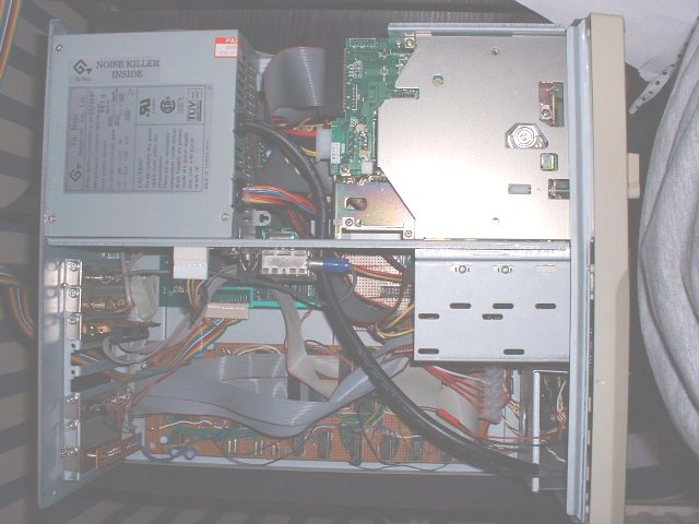
Here's the thing with the lid off. The main board's buried under the standard PC power supply and 5.25" floppy to the top of the picture. The lower half is occupied by my main expansion board. Slap bang in the centre with the blue connector is the cut up TV modulator board (the other half is PSU related and not needed once the PC's PSU is connected).
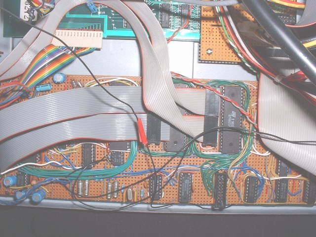
Here's a closer view of my expansion board. It's dominated by the 3 40 pin MC6821 PIAs which are general purpose IO chips for the 68xx processor series. The first one with it's twin light grey cables is connected directly to the back of the case for general purpose parallel communications. One of these forms the PCShare link to my PC. The second one connects to the RAMdisk module (pictured next) via the twin dark cables whilst the third interfaces to an ADC and DAC for digital samples. Most of this circuit is obsqured by the ram disk ribbon cables, although the DAC chip can just be seen.
The large grey ribbon cable to the left of the board covers part of the address decode circuit and bus buffers, although the bulk of it can bee seen below it mostly composed of discrete logic devices up to the small IDC connector. The IDC connector is there to interface to a custom network card. Next to that, the remaining circuitry supports the dedicated sound chip.
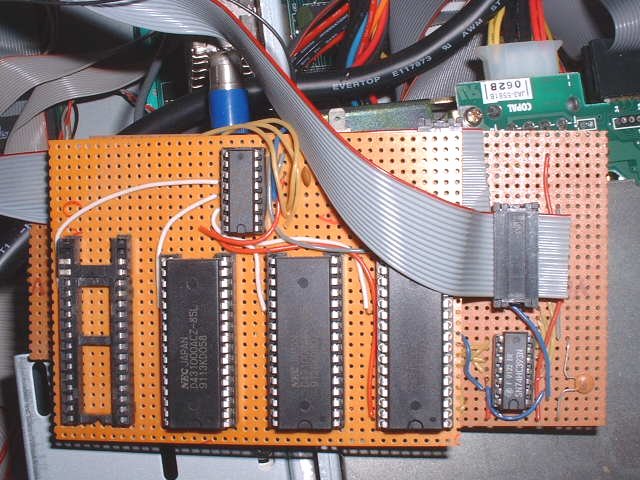
This the the RAM disk board - its a piggy back board, the bulk of the circuit being hidden on the lower card. The upper board shows the 3 128K SRAM devices, with space for a fourth and the decode chip. The ribbon cables seen earlier are shown which connect direct to one of the PIAs.
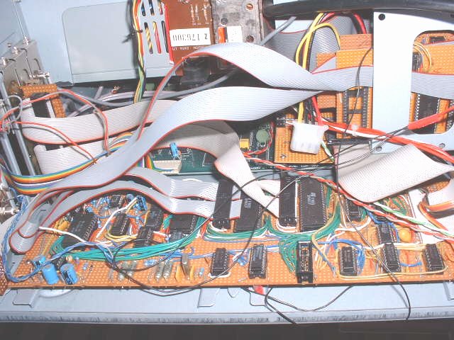
Expansion board again.... The home for the ramdisk can be seen occupying one of the floppy drive bays if you track the twin grey ribbon cables looping over the board. Also to the far right of the board, the large chip now visible is the Real Time Clock (RTC) along with supporting circuitry. There's that modulator board in the middle again....
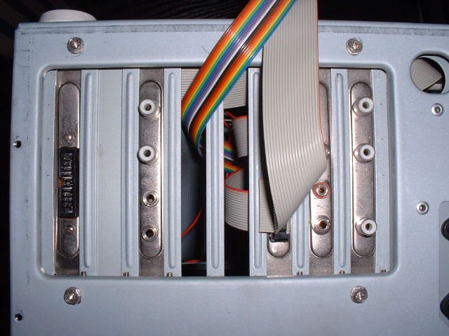
Back of the thing now, most of the connectors are here made possible by cutting up blanking plates for the back plane. Running right to left, the standard 20W IDC printer connector, audio connections comprising 2xphono jacks for the sound chip, 2x3.5mm connectors for the sampler ADC/DAC, multi-coloured ribbon cable for the keyboard (the intention was to one day interface a standard PC keyboard...), twin 20W IDC connectors - 'user ports' obsquered by the ribbon cable connected to one which is the PCShare link.
Next is the tape connector, brought out onto 2x3.5mm and 1x2.5mm connectors and finally the video - a TV phono connector then monitor connector - composite and audio.
The serial port and joystick ports aren't shown, they come out using 9w D-types further along the back.