
| Contents |
| Dragon HW |
| Dragon SW (DDOS) |
| Dragon SW (OS9) |
| Dragon Projects |
Parallel Comms
I have mentioned a number of times repeatedly in the past, the MC6821 PIA - interfacing it and what it does ie. provides 2 eight bit I/O ports at a given address in memory. The data sheet on this chip gives enough detail about what the device provides but essentially the PIA maps into 4 bytes of memory with a control register and an IO register for each port. The control register deals with settings for the port such as interrupt generation & which bits of the port are inputs and which are outputs whilst the IO register actually reflects the status of the port. As an example:
The 'A' side of a PIA is set to be all inputs. A binary number can be input into this port by tieing respective lines to +5V and 0V ie.
PA7 PA6 PA5 PA4 PA3 PA2 PA1 PA0
 0V  0V +5V  0V +5V +5V  0V  0V
in binary 00101100 and decimal 52.
These ports are an easy way of interfacing to computers, since you don't have to worry about data bus speeds, address bus etc etc.
One of the potential uses for these ports is in parallel communications. This method of comms between computers isn't widely used - mainly because of the overhead in cable. It's not too difficult to work out that for parallel communications you need as least 8 wires, whilst for serial you can get away with 3. However, there are distinct advantages in using parallel communications locally between 2 computers. The first is that it is a lot faster since data is sent a byte at a time and the routines are a lot simpler - there are no synchronisation or timing problems involved in breaking up bytes into individual bits. In addition, you don't need complex protocols to manage serial to ensure data integrity.
So much for the benefits of parallel comms... How it works is very simple (much in the same way as the Dragon sends data to it's printer). One computer has an I/O port configured as an input - the other one as an output. In addition there is at least 1 0V line and two control lines (which I shall call CA1 and CA2 since the correspond with the control lines on a 6821). CA2 is an output line and CA1 is an input. Each computer's CA2 line is connected to the oposing CA1 line. 11 lines at a minimum are therefore required for this form of parallel comms. The transfer can now run as follows:
1. Computer 'A' writes a byte to it's output port. In doing so the hardware makes A's CA2 line change state.
2. Computer 'B' waits until A's CA2 line causes B's CA1 line to change. It then reads the input port to obtain the byte just sent.
3. In reading the port, B's the hardware makes B's CA2 line change state.
4. Computer 'A' waits until B's CA2 line causes A's CA1 line to change. It can now loop to step 1 to send the next byte.
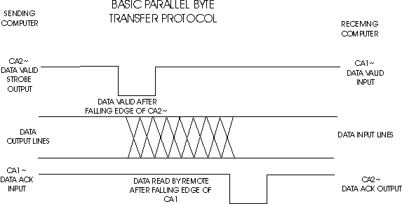
This loop proceeds until all the data is sent. The only limit on the speed, is the slowest of the 2 machines. The entire Dragon's memory could probably be sent in a few seconds.
Two computers which are ideally suited to this form of communications are the BBC Micro and the Commodore 64. The BBC isn't too bad since the Dragon can read it's discs, but with the 64 it's the obvious choice. By building a PIA onto the Dragon you can download data to/from this machine via the CBM 64's user port with a short piece of code written on each machine. Alternatively you could use the printer port on the Dragon (for output only) and re-configure the PIA. The ACK~ line becomes CA1 and you would have to manually flip the STROBE line to act as CA2.
I've listed a few machine code routines, with comments which are essentially the ones I used to transfer data to & from a CBM64 to my Dragon. They're in DASM format, with a a PIA mapped at $FF30-$FF33.
User In - this uses port 'A' as an input port and reads in aaaa bytes and stores them from address bbbb onwards via:
EXEC @RECIEVE,bbbb,aaaa

40 @PARAM JSR $89AA  - parameter routine
50 JSR $8E83           puts 1st value of EXEC
60 PSHS X              into Y register
70 JSR $89AA           and 2nd value in X reg
80 JSR $8E83
140 PULS Y
150 RTS
160 @RECIEVE PSHS U,A,B,X,Y,CC  - start here
170 CLR $FF31  - setup control reg to for data
                 direction setting
180 CLR $FF30  - set for input
190 LDA #47    - control register setting for
200 STA $FF31  - CA2 strobe/CA1 detect
210 BSR @PARAM - get the input parameters
220 ORCC #$50  - turn interrupts off
250 @LOOP TST $FF31  - read control reg to detect
260 BPL @LOOP        - for CA1 going off
270 LDA $FF30  - only if CA1 detected, read byte
                 (CA2 strobes)
280 STA ,Y+    - and store
310 LEAX -1,X  - decrement byte count
320 BNE @LOOP  - if non-zero loop for next
340 PULS A,B,X,Y,U,CC,PC - restore regs & quit
350 END @RECIEVE
User Out - this uses port 'B' as an output port and writes out aaaa bytes from address bbbb onwards via:
EXEC @SEND,bbbb,aaaa

110 @SEND PSHS U,A,B,X,Y,CC - preserve regs
120 CLR $FF33 - setup control reg for data dir
130 LDA #$FF  - code for all outputs
140 STA $FF32 - set port for outputs
150 LDA #47   - control reg setting for CA2/CA1
160 STA $FF33
170 BSR @PARAM - PARAM code as user in routine
180 ORCC #$50  - IRQs off
190 @NEXT LDA ,Y+ - load a byte
200 STA $FF32 - write to port (CA2 strobes)
210 LEAX -1,X - decrement count of bytes to write
220 BEQ @OUT - all written? then quit
230 @LOOP
240 TST $FF33 - test for CA1 detected
250 BPL @LOOP - not detected, try again
260 BRA @NEXT - CA1 detected, send next byte
270 @OUT CLR $FF33 - reset port to input
280 CLR $FF32
290 PULS A,B,X,Y,U,CC,PC - restore regs & quit
300 END @RECIEVE
Printer Out - this uses the method I mentioned previously to set up the printer port as an output port only to transfer data to another computer with a user port set as an input. Called as before EXEC @TRANS,bbbb,aaaa:
160 @TRANS PSHS U,A,B,X,Y,CC - preserve regs
165 ORCC #$50           - IRQs off
190 LDA #55             - enable the ACK line on the port
200 STA $FF21                   (which is CA1)
210 BSR @PARAM          - get the parameters
250 @LOOP LDA ,Y+       - fetch byte
260 STA $FF02           - write to PIA
270 LDA $FF20           - toggle STROBE
280 ORA #2
290 STA $FF20
300 ANDA #$FD
310 STA $FF20
320 @TXACK TST $FF21    - wait for ACK
330 BPL @TXACK
340 LDA $FF20           - read PIA to clear ACK bit
310 LEAX -1,X           - loop till done
320 BNE @LOOP
340 PULS A,B,X,Y,U,PC
Printer In - The only thing that prevents the printer port from inputting data, is the buffer chip sitting next to the port (a 74LS244). On one of my Dragons, where the chip had blown I removed it and placed it with a 20 pin chip socket. By using short wire lengths I linked the input pins to the buffer chip to the output pins, therefore enabling the PIA to be connected directly to the printer port. By re-configuring the PIA as an input data could now be recieved. This routine does even more nasty things to the internal PIA - again keep away from the keyboard whilst it's running! Note: it is not advisable to attempt to drive a printer directly without a buffer chip as you may over stress the PIA.
10 @REC PSHS U,A,B,X,Y,CC  - preserve regs
20 BSR @PARAM           - get parameters
30 ORCC #$50            - IRQs off
40 LDA $FF03            - switch port B to data dir mode
50 ANDA #$FB
60 STA $FF03
70 CLR $FF02            - set all lines to inputs
80 ORA #4
90 STA $FF03            - put port B back to default
100 @LOOP TST $FF21     - wait for STROBE from remote
110 BPL @LOOP
120 LDA $FF20           - read PIA to clear ACK bit
130 LDA $FF02           - read data byte
140 STA ,Y+
150 LDA $FF20           - toggle STROBE
160 ORA #2
170 STA $FF20
180 ANDA #$FD
190 STA $FF20
250 LEAX -1,X           - decrement byte count
260 BNE @LOOP           - loop to get next
270 LDA $FF03           - set port B to Data dir mode
280 ANDA #$FB
290 STA $FF03
300 LDB #$FF            - switch it back to all outputs
310 STB $FF02
320 ORA #4              - switch B back on again
330 STA $FF03
340 PULS A,B,X,Y,U,CC,PC  - pull regs & quit
350 END @REC